Aircraft Pitch Autopilot:
Strong Control & Disturbance Rejection
A closed-loop longitudinal pitch controller for a small Cessna-style aircraft, tuned in MATLAB and Simulink: state-space modelling, hardware realism, wind-gust rejection and a frequency-domain proof of stability.
System Dynamics & State-Space Formulation
The goal was a closed-loop longitudinal pitch autopilot for a small aircraft. Modern aerospace control uses state-space modelling rather than simple transfer functions, because it scales to multiple-input, multiple-output (MIMO) systems and lets you track every internal state.
State-Space Equations
System Matrices
A Matrix · System Matrix
Captures the aircraft's natural aerodynamic properties, damping and phugoid modes. It describes how the open-loop airframe evolves on its own, with no control input at all.
B Matrix · Input Matrix
Defines the elevator's physical control authority over the pitch rate. It maps a single deflection command into the states the airframe actually feels.
C Matrix · Output Matrix
Isolates the specific state we want to measure and control: the pitch angle. It collapses the full internal state down to the one sensor reading the autopilot acts on.
Control Architecture & Simulink Model
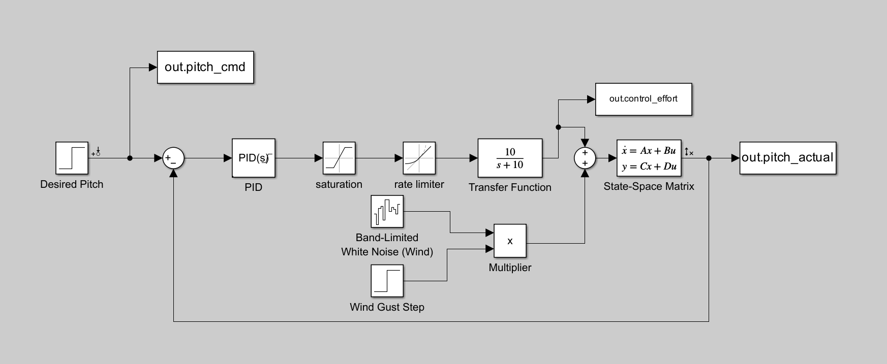
This is the simulinkmodel, reading from left to right. It is sequenced in the way a real control chainruns.
The pitch command is subtracted from the measured pitch angle to form the error signal the controller acts on.
Proportional, integral and derivative gains convert that error into an ideal elevator demand.
Rate and saturation limits clip the demand to what a real servo can physically deliver.
A first-order servo transfer function adds the physical delay.
Band-limited wind noise is summed into the loop to test disturbance rejection.
The clipped, lagged input drives the aircraft state-space plant, which outputs the next pitch state.
The PID Tuning Journey: Human vs. Algorithm
The target was a 0.1 rad pitch command, roughly 5.7°. This is the journey from a first guess, through a failed auto-tune, to the hand-balanced result that worked.
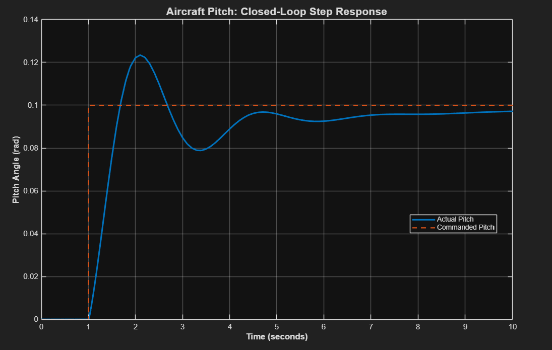
The Aggressive Baseline
High proportional and derivative gains looked right on paper, but the step response showed severe overshoot and a poor steady-state error.
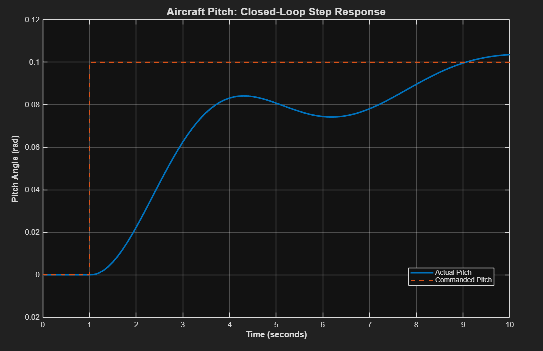
The Algorithm Failure
The auto-tuner assigned a negative D-gain, leaving the loop sluggish and close to unstable.
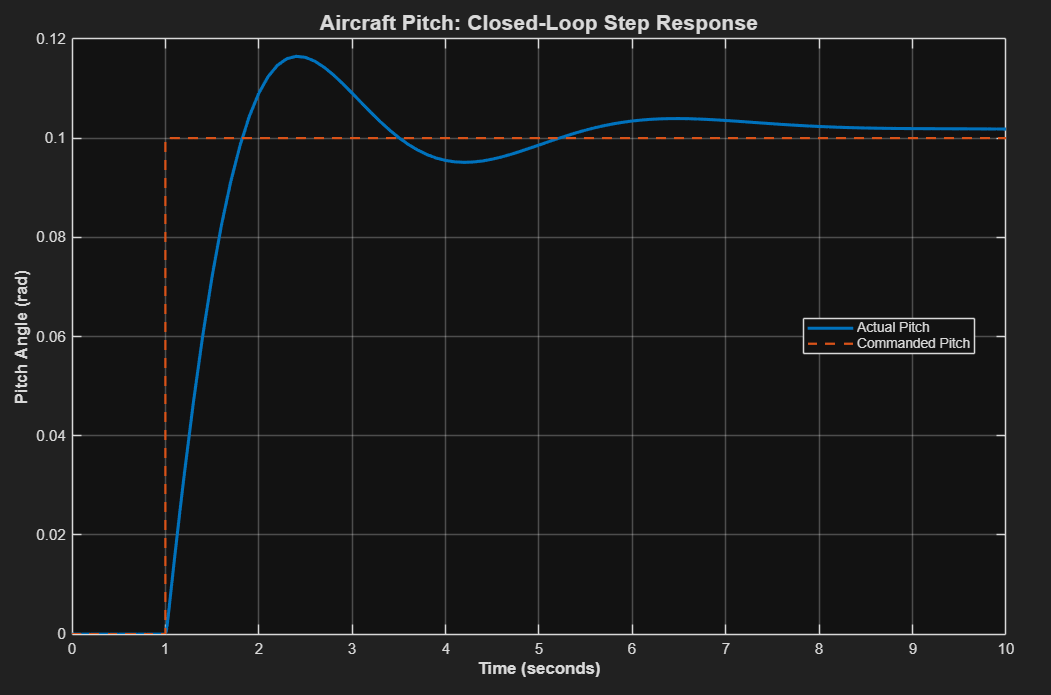
The Engineered Solution
Manual tuning led me to get Kp = 2.7, Ki = 2.1, Kd = 1.5. A fast rise time and a safe overshoot.
Hardware Realism
A purely mathematical controller assumes instant, infinite energy. Real airplanes don't work that way: hydraulic actuators lag, and hinges only travel so far. We need a transfer function
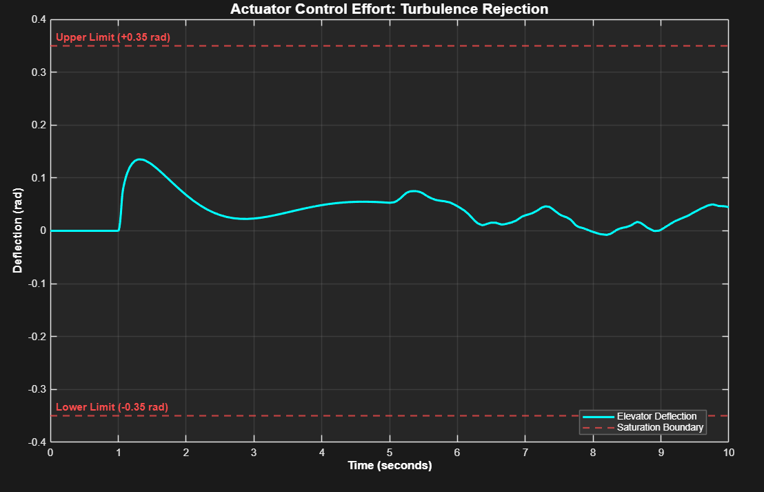
This plot is the proof the elevator never exceeds its physical ±0.35 rad limit, and that it gets there without chattering. The actuator works inside its envelope the whole time, so the servo is not burning itself out to hold the attitude.
Disturbance Rejection: The Wind Gust Test
An autopilot fights weather too. Holding attitude when the air turns violent is what separates a controller that works on paper from one that works on a plane.
A band-limited white noise source models the wind gust, but it is gated with a step multiplier. That gate lets the aircraft fly cleanly for the first 5 seconds before the turbulence is introduced. It isolates the rejection behaviour from the command tracking, so we can see what the controller is fighting.
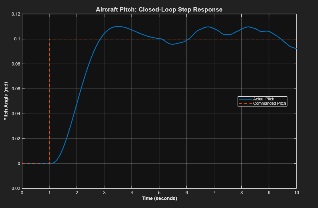
The aircraft's natural inertia smooths the initial gust impact, and the controller fights the residual vibration hard enough to hold the 0.1 rad target. The pitch angle follows the turbulence rather than being driven off by it, which is exactly what you want from a stability augmentation loop.
Frequency Response & Absolute Stability
The time-domain plots look settled, but they only prove this one run is stable. The frequency-domain analysis is what proves the aircraft will not fall out of the sky, because it covers every input, not just the one I watched.
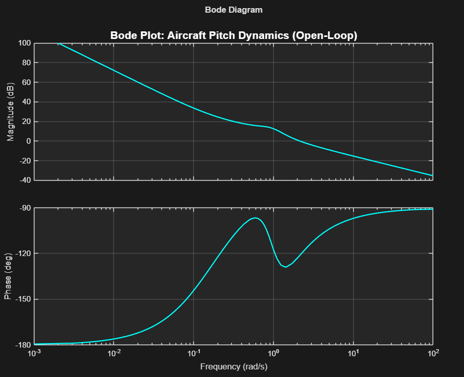
A 61° phase margin leaves a massive buffer against sensor delays and unmodelled lag. Even if the real hardware is slower than the model, the loop stays stable.
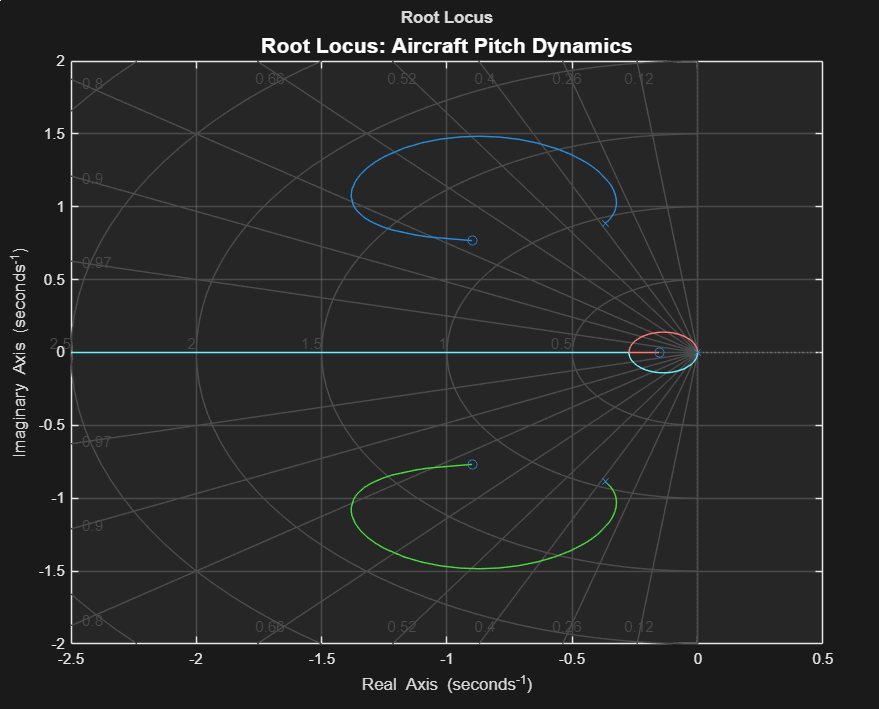
The gain trajectories trace where the closed-loop poles go as the controller pushes harder. Every path stays on the safe side of the imaginary axis, so gain changes move the poles without threatening stability.
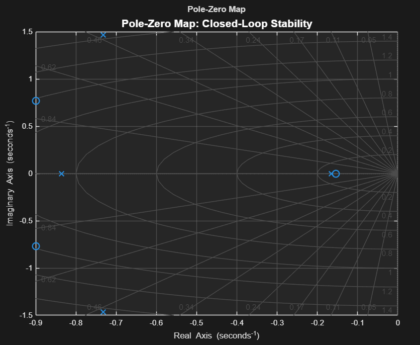
Every blue 'x' pole sits in the Left Half-Plane. That is the absolute, mathematical proof the system is stable.
Future Improvements & Engineering Extensions
The current loop is a validated single-axis baseline. The next steps scale it toward a full flight control system, from outer-loop guidance down to hardware that can fly the real aircraft.
Wrap this pitch controller inside an altitude-command loop as a cascaded PID, so the inner attitude loop becomes the actuator for the outer height loop.
Convert the continuous s-domain controller into a discrete z-domain format, ready to implement on an actual flight computer microcontroller.
Replace the linear state-space model with a full 6-DOF non-linear rigid body simulation, using the Simulink Aerospace Blockset or a live X-Plane integration for real flight physics.

A Sheffield Aerospace Engineering student with extensive CAD, FEA, CFD and MATLAB experience: turning aerospace challenges into validated, optimised designs.