Clevis Bracket
Axial Analysis
A structural optimisation study covering parametric CAD modeling, finite element analysis, fracture mechanics, and data-driven design iteration from concept to validated numerical result.
Component Selection & Design Overview
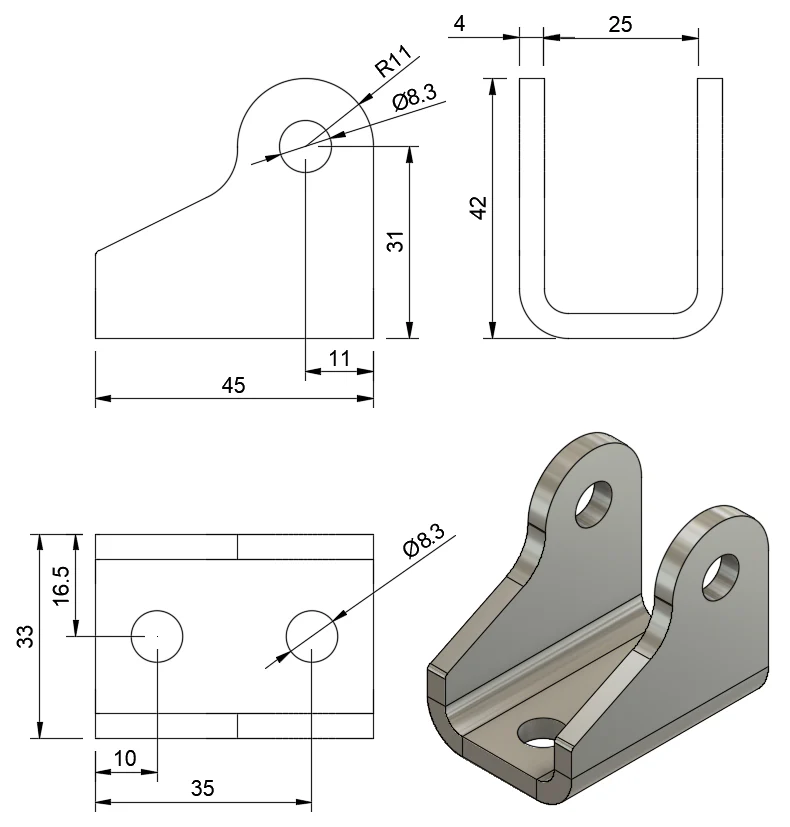
The component under analysis is an industrial linear actuator clevis bracket, engineered to anchor an 8mm mounting pin. Inspired by the Gimson Robotics Stainless Steel A4 Clevis Bracket specification, this study re-evaluates the design from first principles using aerospace-grade materials.
Transfer heavy tensile and compressive axial push/pull forces from an electric actuator directly into a structural chassis, while accommodating angular rotation at the pin pivot joint.
65% lighter than steel baseline
Parametric CAD Modeling Methodology
The bracket was modelled using a dual-method approach designed to build fluency across both machined and fabricated manufacturing workflows.
 Assembly Animation
Machined Billet
- —3D solid extrusions from parametric sketches
- —Boolean subtractive operations for cavities
- —Exact hole features: 8mm pin bore
- —Full associative parametric constraint tree
Fabricated Approach
- —Uniform thickness parameter definition
- —Base tab and contour flange operations
- —Bend radii and K-factor configuration
- —Flat-pattern output for DXF laser cutting
Optimised components were remodelled in Autodesk Fusion to export as .STEP files. Fusion was also used to establish link joints and configure a moving actuation subsystem with full kinematic constraints.
Force Vectoring & Theoretical Calculations
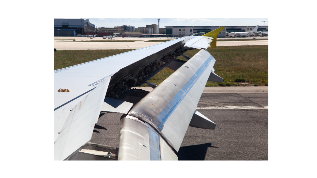
The mechanical physics and trigonometric calculations resolve a multi-axis dynamic actuator force into a pure bearing load. The 10 kN load represents the worst-case load exerted on an aileron control surface during high-velocity manoeuvring: the critical loading scenario for this bracket.
The actuator force is resolved through trigonometric decomposition (cosine projection) to isolate the axial component as the critical bearing load. For this analysis the fully resolved bearing force is F = 10 kN, acting perpendicular to the pin axis on the compressive internal face.
σ_b = F / (d × t)F = Applied Force (N)d = Pin Diameter (mm)t = Bracket Thickness (mm)θ = 15°F_shear = F_axial · sin(15°)F_bearing = F_axial · cos(15°) ≈ 10 kNOnce the kinematic stroke angle is resolved, this 10 kN peak bearing force is what gets driven straight down into the support hole: forming the direct bearing stress input carried through the rest of the analysis.
FEA Boundary Conditions & Numerical Setup
Pre-processing within ANSYS Mechanical establishes the foundation for accurate numerical simulation. Each boundary condition is configured to replicate the physical loading environment.
The structural analysis targets standard aviation acceptance criteria: a Factor of Safety (FoS) of 1.5 on Ultimate Load and 1.15 on Yield Load, in line with FAR Part 25 design philosophies and MIL-HDBK-5J material allowable standards.
 Stress Contour Animation
Applied localized mesh refinement (Face Sizing) around the cylindrical boundaries of the bottom support hole and pin holes to capture high-gradient stress fields accurately. Mesh density increases concentrically toward contact surfaces.
Configured a true parabolic 10 kN Bearing Load acting on the compressive internal face of each pin hole to simulate realistic pin-to-bracket interaction.
Constrained the base mounting holes with fixed zero-displacement boundary conditions (Ux = Uy = Uz = 0), simulating rigid bolt connections to the structural chassis.
Geometric Redesign & Gallery
Initial iterations with sharp 90° internal corners produced catastrophic localised stress concentrations well above the 276 MPa yield limit. FEA showed singularities at geometric discontinuities: stress peaks that would initiate plastic deformation and eventual failure.
The redesign loop in Siemens NX replaced all sharp internal edges with structural chamfers of 1mm radii. This redistributes stress flow lines smoothly across transitions, eliminating singularities and bringing peak stress well below yield.
Data Analytics & Reconciliation
 MATLAB & Python
Raw structural data from the ANSYS design point parameter sweeps was exported and processed in MATLAB: generating curves and identifying where bearing stress crosses the 276 MPa yield limit as bracket thickness varies. Python plotly.js was used to generate embedded interactive graphs for display.
Custom MATLAB scripts generated the stress-vs-thickness curves, computed the structural efficiency metric (yield margin per unit mass), and identified the crossover where the chamfered design satisfies the yield constraint.
Below 276 MPa
At 6.6 mm, the chamfered design drops below the 276 MPa yield limit, maximising the Structural Efficiency Metric: the optimal balance between minimum weight and structural integrity.
Crack Propagation Analysis

Using formulae from the University Aerospace Materials module, transitioned from yield-based design to Damage Tolerance Analysis: evaluating how the bracket behaves if a microscopic defect develops at the high-stress bottom support hole, and determining the critical crack length before catastrophic fracture.
K_I = C · σ · √(π · a)a = Crack length (m)σ = Background stress (Pa)C = Geometry correction factorC = 1.12 − 0.231(a/W) + 10.55(a/W)² − 21.72(a/W)³ + 30.39(a/W)⁴As part thickness decreases, background stress σ spikes exponentially. This accelerates the stress intensity K_I at the crack tip, causing the part to reach the critical 29.0 MPa√m threshold and fracture at microscopic, undetectable crack lengths: in some cases below 0.5 mm. This establishes a hard lower bound on thickness that pure yield-based optimisation cannot capture.
Future Improvements & Extensions
The current analysis establishes a numerical baseline. The following steps will close the gap between simulation and physical reality.
Applying generative AI-driven algorithms to remove un-stressed material from the bracket: creating a lattice structure that maintains full load paths while reducing mass.
Running a full S-N (Wöhler) curve simulation to test bracket life under millions of reciprocating actuator strokes. Establishes the endurance limit and predicts cycles to failure at the operating stress amplitude.
Using a physical load frame with bonded strain gauges at critical locations to validate the FEA data against real-world measurements. Target correlation within 5–10% to confirm model fidelity.

A Sheffield Aerospace Engineering student with extensive CAD, FEA, CFD and MATLAB experience: turning aerospace challenges into validated, optimised designs.