e-VTOL Propeller
Design & Simulation
A computational aerodynamics study of an e-VTOL rotor, from parametric Fusion 360 blade lofting through periodic MRF meshing to a steady-state ANSYS Fluent validation of hover thrust against the DJI Inspire 1 drone.
CAD Modeling & Domain Extraction
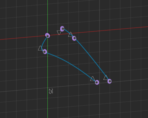
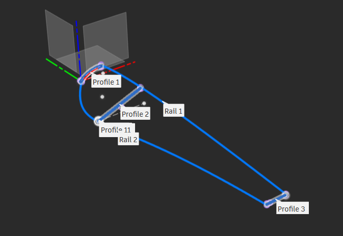
The propeller blade was sculpted parametrically in Fusion 360. Aerodynamic guide rails, offset planes, and lofted splines were used to sweep the blade twist and chord distribution along the span, giving full control over the aerodynamic shape from root to tip. The reference used was the DJI Inspire1, a "powerful" drone "providing the stability" needed (https://www.dji.com/uk/inspire-1/aircraft, 2026)
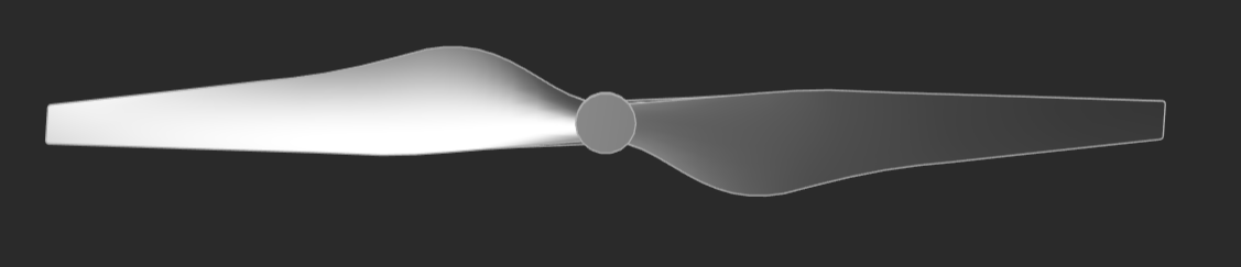

Two distinct fluid enclosures were created in SpaceClaim: a rotating inner cylindrical domain for the Moving Reference Frame (MRF) and a large stationary far-field domain to accurately simulate the open-air environment without wall interference.
A cylindrical enclosure hugs the propeller swept volume with a 4mm clearance. This region is assigned the rotational frame velocity (2000-5500 rpm), feeding the MRF source terms without a sliding mesh interface.
A large open-air volume surrounds the rotor, sized so that pressure and velocity gradients decay to freestream well before the outer boundary, preventing artificial wall confinement of the slipstream.
Meshing Methodology & Boundary Conditions
The meshing strategy balances blade resolution against global cell economy. Local surface sizing concentrates elements where the aerodynamic gradients are sharpest, while periodic symmetry halves the required domain.
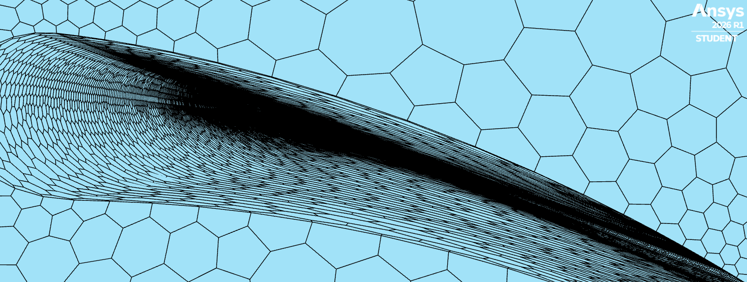
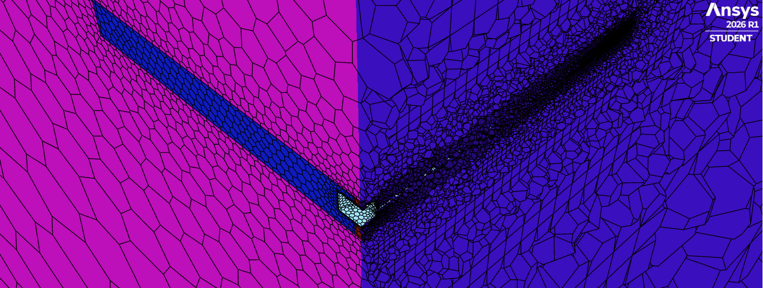
Modeling a half-propeller using periodic boundary conditions reduces cell count by 50%. Local surface sizing was applied to the blades to sharply resolve the complex leading and trailing edges without unnecessarily increasing the global cell count over 512,000 (the student maximum).
A Polyhexcore volume mesh was generated with boundary layers sized to maintain y+ < 5, critical for the SST k-ω turbulence model to accurately resolve viscous sublayer friction and flow separation.
The far-field boundary was set to pressure outlet at atmospheric conditions, the periodic faces paired by rotational periodicity, and the MRF inner domain assigned a rotational velocity of 2000 RPM and 5500 RPM across two design points.
Kinematics & Flow Visualisation
Instead of a transient sliding mesh, steady-state mathematical frame motion was applied to the rotary domain at 2000 RPM and 5500 RPM, allowing for rapid, time-averaged flow convergence.
Isometric slipstream acceleration through the rotor disk.
Top-down view of the helical tip-vortex shedding pattern.
These animations visually prove air acceleration and highlight the tip vortex that dominates the propeller wake structure.
The inflation layer sizing was validated post-solve: wall y+ sits predominantly below 3 and never exceeds 5 across the blade surface, keeping every cell within the viscous sublayer the SST k-ω model demands for accurate skin-friction prediction.
Isometric y+ contour over the rotating blade surface.
Quantitative Validation & DJI Comparison
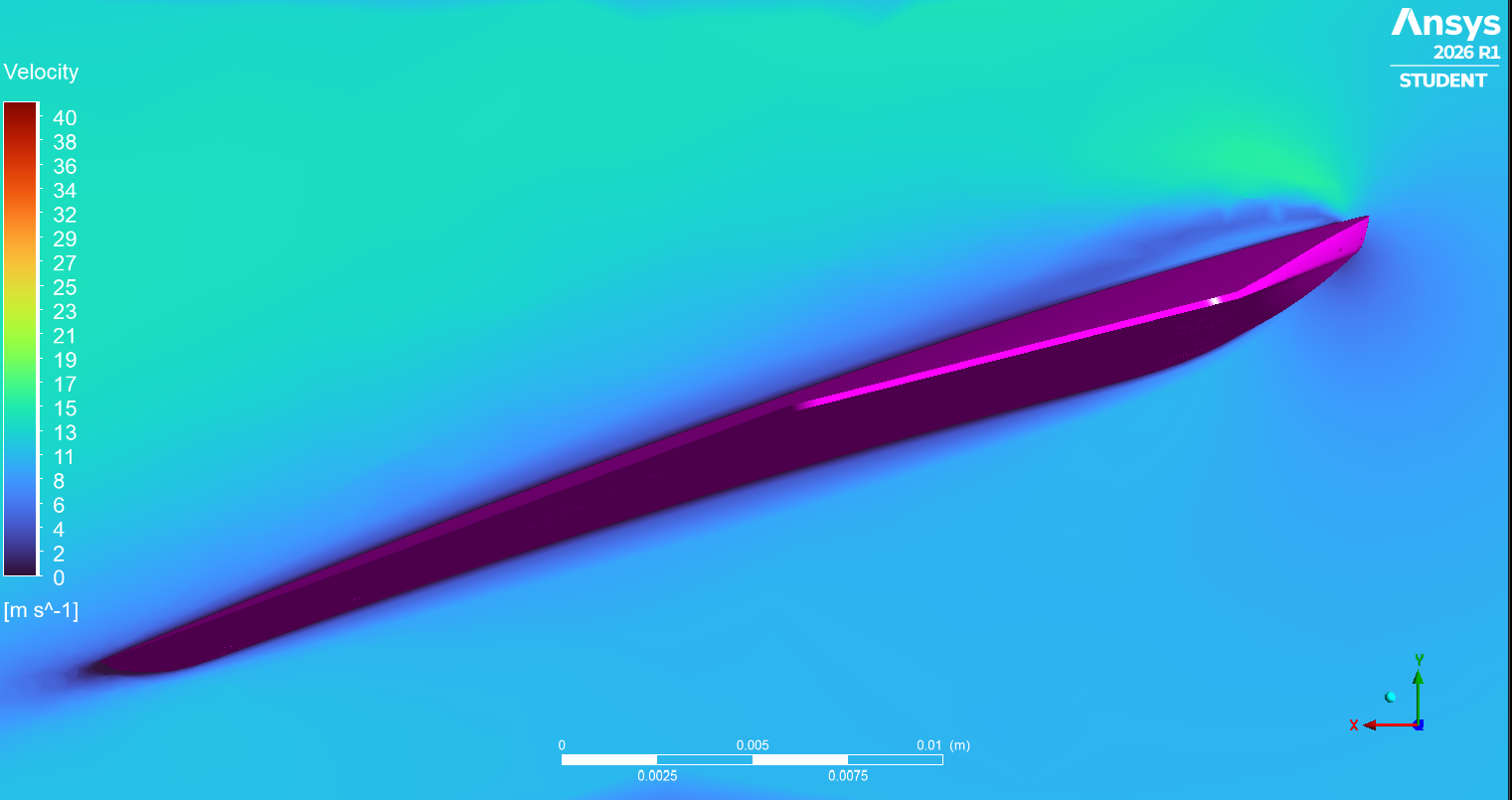
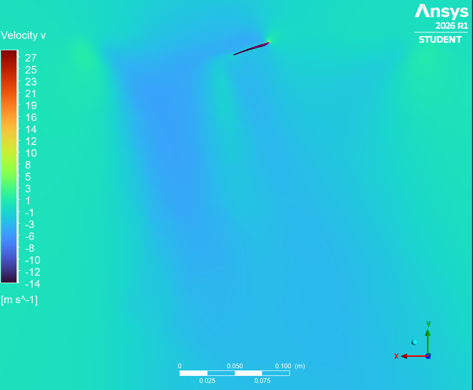
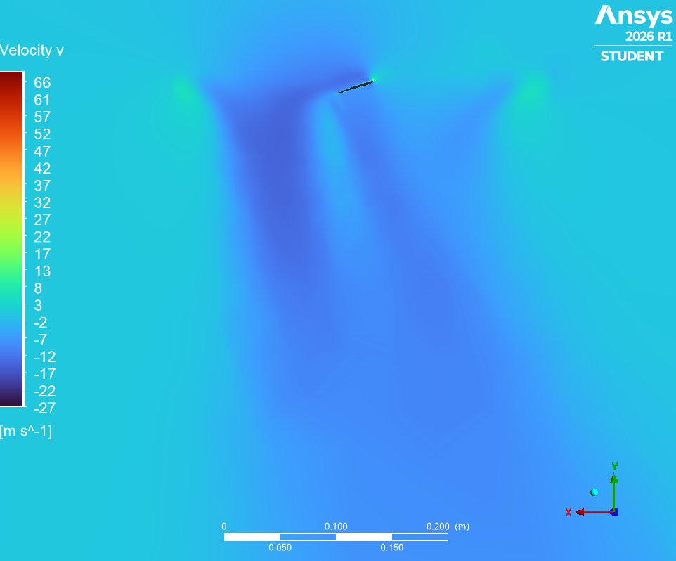
At the leading edge, the flow splits and creates the stagnation point (the red area of high static pressure). Immediately after, the flow has to accelerate around the curvature of the leading edge, so there is an area of low static pressure according to Bernoulli's principle.
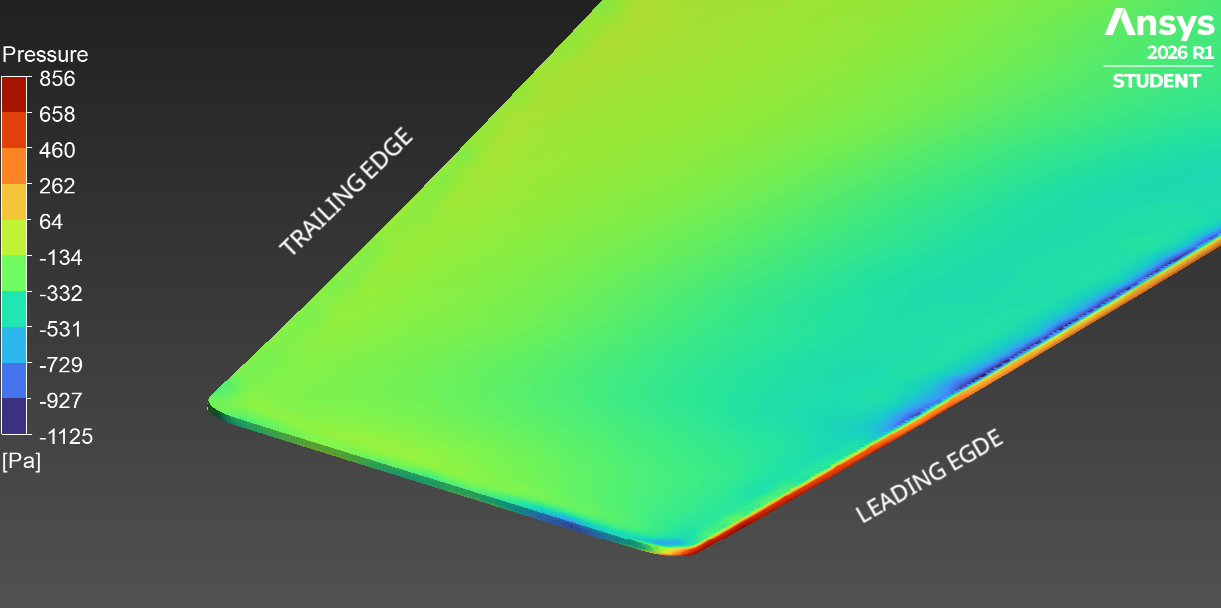
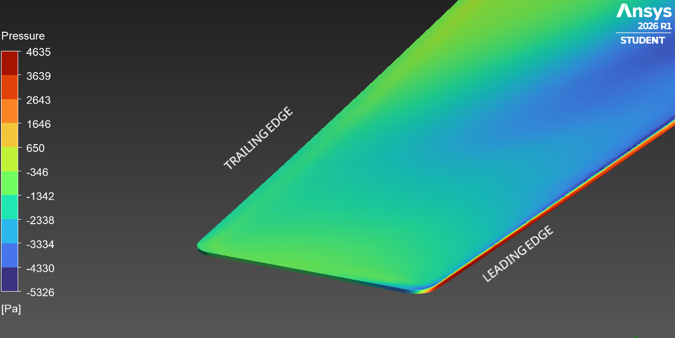
The final loads were extracted from the converged steady-state solution across both design points.
- Force (N)
- Torque (Nm)
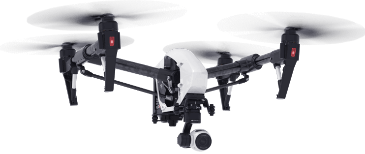
The 5500 RPM thrust data was compared against the DJI Inspire 1, which weighs 3060 g (requiring 7.50 N thrust per propeller). While the model proves accurate scaling from 2000 RPM to 5500 RPM (thrust scales as rpm squared), the force is underpredicted likely because the mesh density in the wake was too coarse to capture full momentum transfer with the student limit.
Wake mesh too coarse
Future CFD Extensions & Next Steps
The current MRF baseline establishes a validated steady-state foundation. The following steps extend the study toward better transient modelling and physical accuracy. Currently, these options will not be possible in Ansys student mode due to maximum cell counts. Scaling up to larger models and full aircraft would also be desirable.
Transitioning from the steady-state MRF approximation to a fully transient Sliding Mesh model to capture time-dependent rotor interactions, true unsteady vortex shedding, and blade-pass frequencies.
Implementing downstream volumetric density boxes and Adaptive Mesh Refinement (AMR) to prevent numerical dissipation of the tip vortices. This will capture the full momentum transfer, closing the gap between the simulated 2.5 N thrust and the DJI Inspire 1 flight requirements.
Utilising the Ffowcs Williams-Hawkings (FW-H) acoustic model on the transient data to predict broadband and tonal noise generation: a crucial certification design constraint for e-VTOL aircraft and drones.

A Sheffield Aerospace Engineering student with extensive CAD, FEA, CFD and MATLAB experience: turning aerospace challenges into validated, optimised designs.