Hydrogen Combustion Chamber
Design & Simulation
A dynamic CFD and thermal study of a hydrogen-fuelled internal combustion chamber: reverse-engineered from a geometry, rebuilt as a fully parametric Fusion model, and cycled through a 6000 RPM transient simulation in ANSYS Fluent with dynamic meshing and a 3000 K spark.
Component Selection & Design Overview
My objective was to model and simulate a hydrogen-fuelled internal combustion chamber. The initial methodology was reverse-engineering. A baseline .STEP file from an existing engine model was taken as the starting point, then the geometry was completely rebuilt to match the exact target specifications while introducing fully parametric controls. Rather than locking in a single design, the rebuild made every driving dimension a user parameter, so fin geometry, valve sizing and cylinder proportions could be adjusted without redrawing a sketch.
Parametric CAD Modelling Methodology
The entire chamber was designed to be fully adaptable in Fusion using user parameters.
The internal components were assembled with explicit joint configurations linking the piston head, connecting rod and bolt. These joints were configured to guarantee the correct kinematic translation of the piston through its stroke, so the same motion could later be mimicked by the dynamic meshing in Fluent.
Kinematic assembly motion of the piston head, bolt and connecting rod, prepared for dynamic meshing.
Parametric Design Iteration Gallery
The flexibility of the parametric Fusion model is shown below. Each view is generated from the same master file by changing user parameters only: no sketch was redrawn, no feature was rebuilt manually. This is the same chamber driven by different fin, valve, top-profile and cylinder-diameter values.
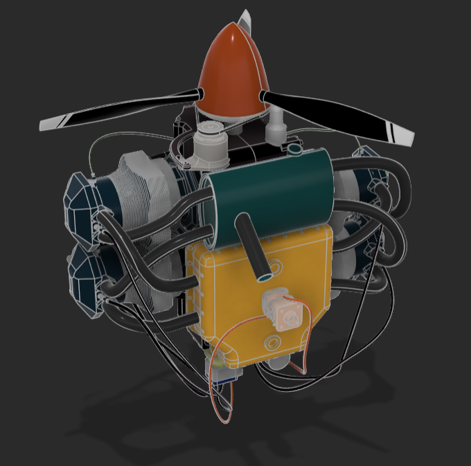
The complete parametric engine assembly.
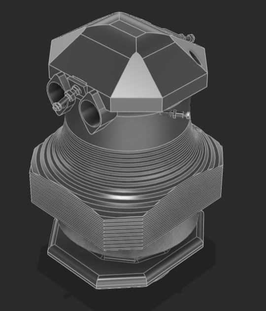
The combustion chamber isolated from the full assembly.
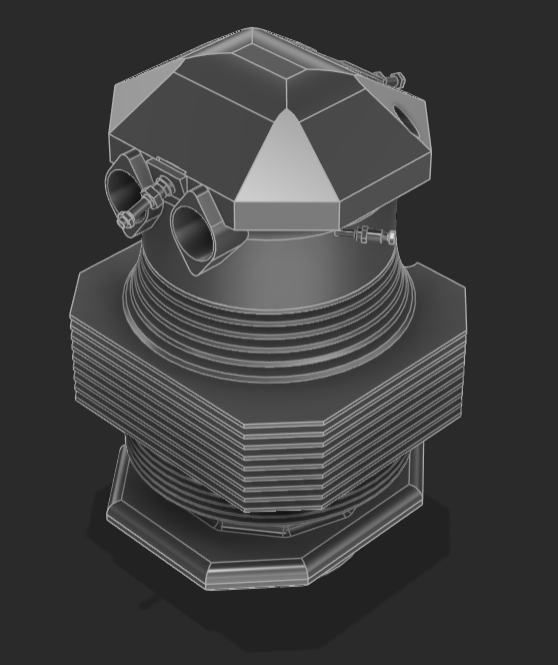
Chamber iteration with a different fin shape and fin count.
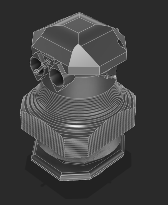
Chamber iteration with different valve sizes and top profile.
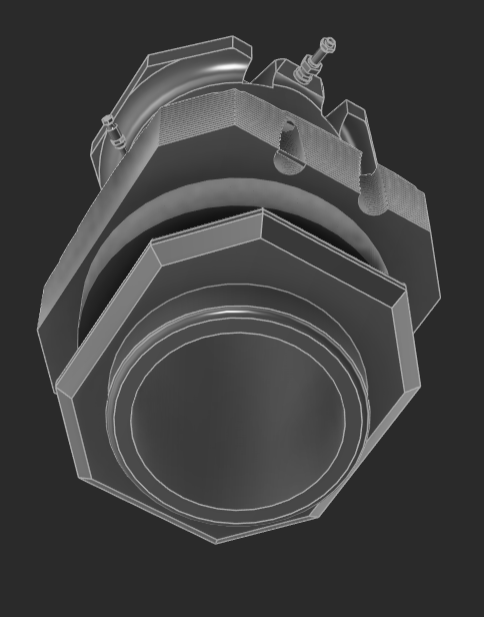
Bottom view of the baseline chamber.
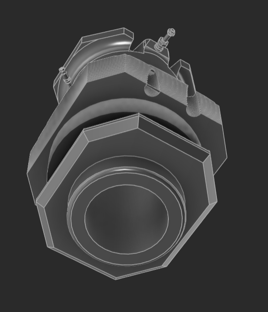
Bottom view iteration with different cylinder diameters.
CFD Boundary Conditions & Setup
Dynamic meshing was used to handle the moving boundaries of the fluid domain as the piston cycles at 6000 RPM. Rather than a fixed grid, the mesh layers are added and removed in real time to follow the piston motion, preserving cell quality through the full stroke without remeshing the whole domain each step.
The transient simulation captures six distinct phases of the operating cycle in sequence:
Piston rises, compressing the hydrogen-air charge ahead of ignition.
3000 K boundary / source term initiates combustion at top dead centre.
Flame front develops and sweeps across the compressed charge.
Hot combustion products expand, driving the piston downward.
Cylinder vents and begins re-compressing the fresh charge.
Cycle closes with the second expansion before the loop resets.
The combustible mixture was initialized with a 0.081 hydrogen mass fraction: the baseline charge composition seeded across the fluid domain before the compression stroke begins.
Thermal Analytics & Combustion Visualisation
The thermal results extracted from the Fluent solver focus on flame front development and heat distribution within the cylinder during the ignition phase. The temperature contours trace how the 3000 K spark kernel grows into a propagating flame and how the heat then spreads through the expanding charge.
3D fluid cylinder animation showing temperature contours across the full volume, focused on overall volume thermodynamics.
2D cross-section through the centre, focused on the 3000 K spark ignition point and the immediate expansion wave.
Future Improvements & Engineering Extensions
The current dynamic-mesh system establishes a validated transient combustion cycle. The following steps extend the study toward thermal analysis, emissions modelling and intake flow optimisation.
Exporting the thermal loads from Fluent back into structural FEA to analyse thermal fatigue and stress concentrations on the chamber walls under cyclic peak temperatures.
Implementing chemical kinetics models in Fluent to track potential Nitrogen Oxide emissions at high peak temperatures, a key sustainability and regulatory constraint for hydrogen combustion.
Simulating the fluid flow through the parameterised valves to measure and optimise efficiency and turbulence kinetic energy in the cylinder prior to the spark event.

A Sheffield Aerospace Engineering student with extensive CAD, FEA, CFD and MATLAB experience: turning aerospace challenges into validated, optimised designs.