Shock-Wave / Boundary-Layer
Interaction at Compression Ramps
A supersonic CFD study of shock-induced flow separation at a 24° compression ramp, validated against high-speed schlieren experiments and resolved with a density-based, convergence-stabilised ANSYS Fluent workflow.
Aerodynamic Context & Experimental Baseline
Shock-wave/boundary-layer interactions (SWBLI) at compression ramps are a critical phenomenon in supersonic aerodynamics, governing the performance of supersonic engine inlets and control surfaces. The impinging shock creates severe adverse pressure gradients that force the boundary layer to separate, producing aerodynamic drag, flow unsteadiness, and potentially catastrophic inlet unstart.
Shock-Wave/Boundary-Layer Interactions at Compression Ramps Studied by High-Speed Schlieren
Sun, Z., Gan, T., & Wu, Y. — AIAA Journal, Vol. 58(4), 2020
The CFD model was validated against this benchmark study, which uses 20 kHz high-speed schlieren to capture the unsteady separation shock dynamics across two Reynolds number regimes at Mach 2. The AIAA Journal is a peer-reviewed scientific journal.
View DOIComputational Domain & Meshing Strategy
The 2D domain was constructed in ANSYS SpaceClaim, defining an upstream flat-plate length sufficient for a fully developed turbulent boundary layer to form before the compression ramp corner, with a downstream extent large enough to capture the reattachment shock and exhaust without reflective boundary contamination.
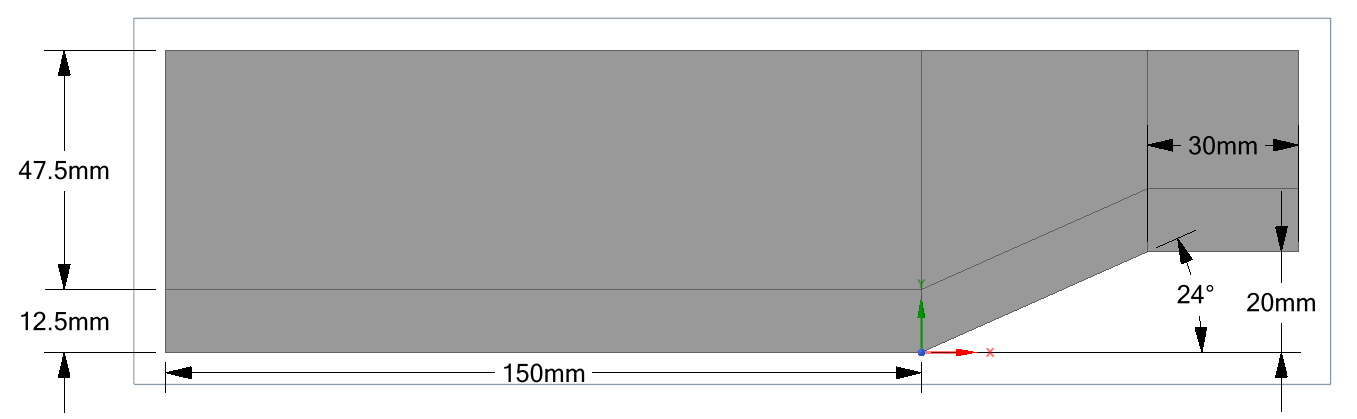
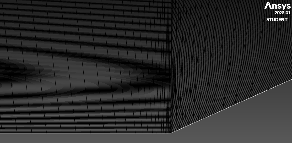
Edge sizing was used to heavily concentrate elements around the ramp corner and the anticipated shock-foot locations, resolving the sharp gradients of the oblique shock and the separation region without smear.
A biased inflation layer resolved the viscous sublayer to a target wall y+ ≈ 1, accurately capturing flow separation, skin friction and shear stresses within the separated bubble.
ANSYS Fluent Solver Methodology
A density-based solver was used. This is mandatory for capturing the highly compressible, supersonic shock structures that dominate this flow. The coupled pressure-velocity formulation resolves the strong compressibility coupling that a pressure-based solver would smear across the shock front.
The simulation was initially run using a 1st-order upwind spatial discretisation scheme to establish the basic supersonic flow field and prevent early divergence from under-resolved shock gradients.
Once the residuals steadied, the solver was transitioned to a 2nd-order upwind scheme to crisply resolve the shock waves and minimise numerical dissipation, recovering the sharp density jumps observed in the schlieren.
Kinematics of the Separation Bubble
When the adverse pressure gradient driven by the shock propagates upstream through the subsonic portion of the boundary layer, it forces the flow to separate and curl back on itself, forming a closed recirculation bubble ahead of the ramp corner. This is the cause of the interesting phenomenon.
Full domain streamlines interacting with the compression ramp.
Close-up of the shock-induced separation bubble and loop backflow.
Transient Dynamics & Shock Oscillation
The SWBLI is inherently transient. The separation shock exhibits low-frequency broadband oscillations driven by the expansion and contraction of the separation bubble, a phenomenon documented in the Sun et al. study and reproduced in the present CFD. However, when running a transient simulation in Ansys, the turbulent eddies couldn't dissipate energy outwards in the Z direction so the separation bubble inflated instead of oscillated. To simulate the oscillation, the research paper mentions Direct Numerical Simulation (DNS) and Large-Eddy Simulation (LES) would be required. While these methods would improve the solution, they were too computationally expensive for me currently..
Transient Mach contour evolution.
Unsteady shock-wave growth tracking.
Experimental Validation & Reconciliation
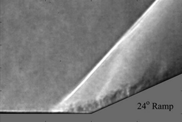
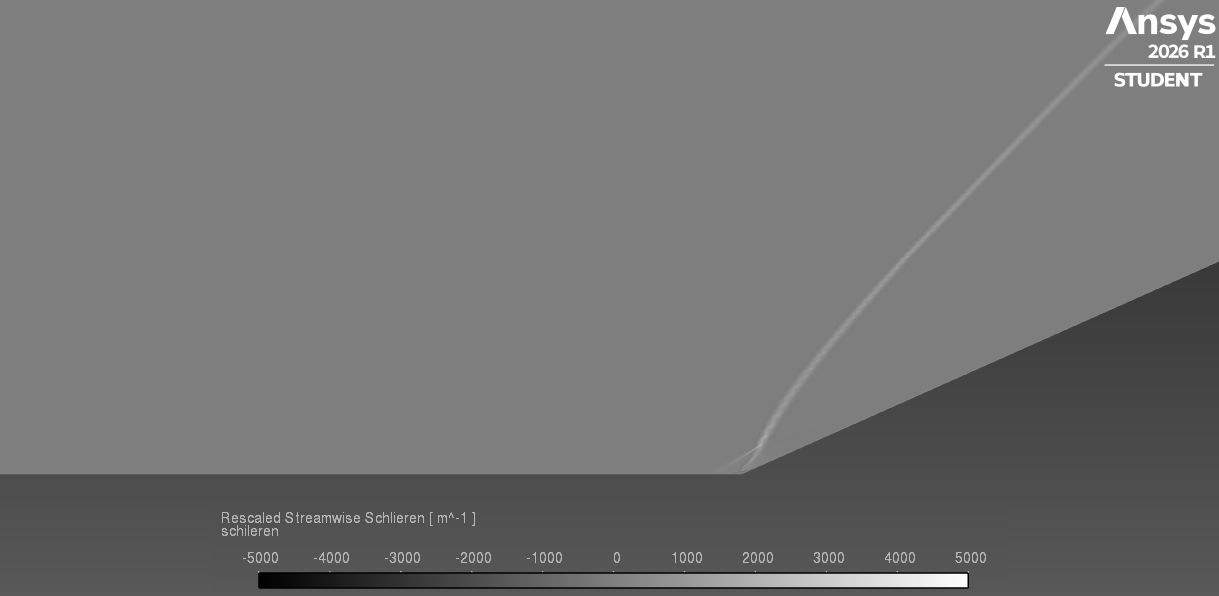
The CFD density-gradient field was compared directly against the 20 kHz schlieren snapshots from the Sun et al. paper. The separation shock angle, separation bubble length, and reattachment shock configuration all matched the experimental record closely.
Exact agreement
Future CFD Extensions
The current RANS baseline establishes a validated foundation. The following iterative steps extend the study toward higher-fidelity turbulence modelling and active flow control.
Large-Eddy Simulation (LES)
Transitioning from RANS to LES to capture the highly unsteady, three-dimensional turbulent structures inside the separated shear layer and resolve the broadband shock motion directly.
Reynolds Number Sweep
Running parametric sweeps to match both Re₁ (18,600) and Re₂ (35,600) from the literature to study interaction length scaling and bubble growth with Reynolds number.
Thermal & Separation Mitigation
Introducing active flow control (micro-vortex generators or bleed slots) to minimise the separation bubble size and reduce shock-induced drag and unsteadiness.

A Sheffield Aerospace Engineering student with extensive CAD, FEA, CFD and MATLAB experience: turning aerospace challenges into validated, optimised designs.
- [1]
Sun, Z., Gan, T., and Wu, Y., 'Shock-Wave/Boundary-Layer Interactions at Compression Ramps Studied by High-Speed Schlieren,' AIAA Journal, Vol. 58, No. 4, 2020. https://doi.org/10.2514/1.J058257